Hardware Development – Motor Simulation
This week, I’m writing the code for the motor and try to simulate the program using Proteus. Initially, the motor didn’t work and Proteus simulation log displays “Simulation not running in real time due to excessive CPU load”. I’m not sure how this happened, is it the program or is it the simulation circuit. I tried to goggle on the internet searching through forums and etc, however the solutions given still did not make any changes to my simulation results. Therefore, to solve this problem, I tried to simulate the sequence of the motor manually by using logic state as below.
 |
| Motor at position 0/360 degree |
|
|
 |
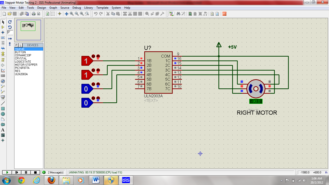
| Motor at position 45 degree |
 |
| Motor at position 90 degree |
 |
| Motor at position 135 degree |
 |
| Motor at position 180 degree |
 |
| Motor at position 225 degree | |
|
|
|
|
|
|
|
 |
| Motor at position 270 degree |
 |
| Motor at position 315 degree |
The negative sign in the simulation shows that the motor turns counter clockwise (CCW). From this simulation, the sequence of the motor can be summarized as below:
| Turning Position (degree) | Input sequence for ULN2003A |
| 1B | 2B | 3B | 4B |
| 0°/360° | 1 | 0 | 0 | 1 |
| 45° | 1 | 0 | 0 | 0 |
| 90° | 1 | 1 | 0 | 0 |
| 135° | 1 | 1 | 1 | 0 |
| 180° | 0 | 1 | 1 | 0 |
| 225° | 0 | 1 | 1 | 1 |
| 270° | 0 | 0 | 1 | 1 |
| 315° | 0 | 0 | 0 | 1 |
I did 2 types of circuit in Proteus to test the motor, one with ULN2003A and without ULN2003A. This is to test and see the difference in terms of input and output and I noted that the simulation using ULN2003A will inverse the output from ULN2003A.
 |
| Circuit with ULN2003A |
 |
| Circuit without ULN2003A |
There are also two types of programs using assembly and C. The program using assembly able to simulate the circuit until +45° while the program using C manage to simulate the circuit successfully (thank you to my supervisor for his assistance). There are several factors that results in simulation failure in this project. The failures are summarized as below:
| No. | Problem | Caused | Solution |
| 1. | The motor turns CCW but stop at 112°. | Wrong connection between B1 and BC of the motor. | Rewire the circuit. |
| 2. | Simulation stop or did not work and simulation log display “Simulation not running in real time due to excessive CPU load”. | The instruction cycle running too fast. | Reduce the oscillator value or try to create a longer delay. |
| 3. | Motor did not turn smoothly. | Delay is too long or too short. | Change the delay and test until you get the suitable value. In this case, the appropriate delay is 500ms. |
| 4. | The circuit able to simulate until 45° and stop. | The oscillator used in this circuit is too small 1kHz plus a longer delay in program. | The oscillator should be increased to 4Mhz and the delay is adjusted accordingly. |
As a conclusion, simulating the circuit before testing on your hardware gives a lot of benefit in terms of error detection either in program or in circutry and reduce the time consume in hardware development. Error detection or circuit malfunction is more difficult to be traced and time consuming in hardware troubleshooting as you have to troubleshoot each part of the circuit.