Wednesday 30 November 2011

Week 5: August 22 to August 28, 2011


Literature Review

Project Tittle: The Inception of Chedda: A detailed Design and Analysis of Micromouse
Author: Tondra De & Drew Hall

Hardware Development

The authors have decided to use stepper motors due to its precise movement control. Stepper motors can move in very small incremental steps as well as hold their position and resist turning, makes them perfect for Micromouse application. Bipolar steppers are stronger than unipolar steppers of the same size and weight because they have two times the field strength in their poles (single windings without a centre tap). Since space and weight are important constraints for the Micromouse, they have opted to use 2 units of bipolar hybrid stepper motors rated at 12 V DC and 400 mA. The motor controller selected for this project was Allegro 3967 which have continuous drive capability of 750 mA with a peak of 850 mA which is capable for handling higher current spikes during initial starting of the motor or if the motor becomes stalled, thus help to keep power dissipation at a reasonable level. 

Bipolar Hybrid Stepper Motor from Jameco Electronics


Since the Micromouse needs to run at full operation for around 20 minutes at a time, a battery capacity of around 300 mAH is required. Batteries with the smallest possible internal resistances are preferred to allow for the potential current surges. Another two significant practical issues that need to be considered regarding the selection of batteries are their size and weight since the space of batteries are quite limited and the mass of the batteries should have a lower weight to decrease the burden of the load on the motor torque. Finally, rechargeability is also an important property of battery that should be taken into account since the robot would operate for extended period of time. Therefore, the authors decided to use lithium polymer batteries with capacity of 1.2 Ah, 7.4 V DC and maximum current of 10A which capable to fulfil the power requirement of the robot. The lithium polymer batteries are selected due to their small size, compact and have the highest energy density of any currently available battery.

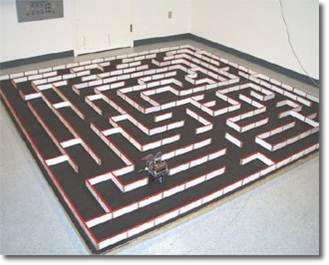
 To achieve its goal of travelling to the centre of the maze, the Micromouse may require the sense of sight and/or touch, depending on the sensor technology (or combination of technologies) used. The sensor technology used in this project is infrared sensor technology and the sensors used are Sharp GP2D120 short-range infrared sensors for sensing distance to the walls of the maze. These IR sensors output a voltage relative to the distance of the sensor from an object ahead.

Sharp short-range infrared sensor


A separate independent odometry was added to measure the distance travelled by the robot using a shaft encoder, which is a special sensor that measures the position or velocity of a rotating shaft. It is mounted on the output shaft of a motor.

The chassis of the robot is made of polyvinyl chloride (PVC) plastic because it has a good weight to strength ratio.


Sunday 27 November 2011

Week 4: August 15 to August 21, 2011

Literature Review

Book tittle: Embedded Systems and Robots Projects Using The 8051 Microcontroller
Author: Subrata Ghoshal 
Project tittle: Maze-Solving Robot Using Wall-Following Algorithm


A wall-follower robot follows the wall at its left (or right) blindly from the start to finish. If it starts following the right wall then it must stick to this wall till it reaches its destination. Once decided, the selected side is not allowed to change. However, the wall-following method is inefficient and does not work for IEEE mazes because the finish point is at the centre of the maze and they are specifically designed to prevent wall-following from succeeded. Nevertheless, certain techniques and methods can still be applied to Micromouse. 


Hardware Development

The maze-solving robot by Subrata Ghoshal used 2 units of toy cars, each powered by a single DC motor. The toy cars were cut into half and joined together to obtain a differential drive required to turn the car clockwise or anticlockwise. LDR’s were used for sensing the sidewalls while a touch sensor, a type of mechanical switch generally used in the computer keyboard was used to sense the front wall. The mechanical switch was used due to its cost-effectiveness and lesser number of hardware parts needed to make it function compared to LDR. Extra LDRs (ALARM LDR) were used on both sides of the robot to measure the proximity of the wall being followed. If the wall is too close, it would immediately be activated and sent signal accordingly. Otherwise, it should remain switched off. The robot was powered by 6 V power cell for motor and 9 V power cell with 7805 voltage regulator to supply a regulated 5 V DC power to the controller circuit. The controller circuit consists of AT89C2051 as the microprocessor.

The size of the robot is crucial to allow smoother negotiations through bends and turns. According to the designer, the size of the robot should not be more than one-fourth of the cell size. That is, for a maze with 180 mm x 180 mm grid, the robot size should be 90 mm x 90 mm or less at its base.

Software Development

Most of the time, the robot would move forward following a wall. The speed was controlled using Pulse Width Modulation (PWM) at 50% duty cycle. In case of reverse movements which adopted when the robot confronts a wall, slower speed is desirable and PWM is applied. For right and left turns, PWM is not necessary; only one motor is moved with full speed, while the other is not activated at all.

To ensure that the turn angles are exactly equal to 90º, the concept of time constant is used. Trial-and-error method is used to find the accurate time constant value. To finalize the time constant value for a 90º rotation, the robot is allowed to move forward for some time and then take a turn. The whole process is then repeated again and again (infinite loop). If the time constant adopted for this process is correct, then the robot would be moving along a perfect square for at least fifty loops. This time constant depends upon various parameters such as the make of the motor, its operating voltage, self-weight of the robot and friction against the floor.

The touch sensor is interfaced with INT0 input of the controller.

The overall program structure started with reset initialization followed by checking port 1.1 jumper setting to determine either to follow right wall or left wall, and start moving forward with PWM. The program then enters into an infinite main loop where the existence of a sidewall is continuously sensed during the forward movement. In the absence of any wall at its side, the robot would perform turning operation. Whenever the robot encounters a front wall, the INT0 interrupt service routine takes over the charge of reversing the robot and then turning it. Finally, the robot is set for forward operation and the duty of the INT0 interrupt is complete.

Thursday 24 November 2011

Week 3: August 8 to August 14, 2011


Micromouse
 
A Micromouse is a miniature electro-mechanical robot, typically consisting of three main subsystems:
  1. The drive system
  2. An array of sensors, and
  3. The control system. 

Airat 2 by Microrobot

Tetra Micromouse

Maze

A competition standard Micromouse maze contains 16 cells north-south, and 16 cells east-west. Each maze cell is 180 mm x 180 mm including the walls, with a maximum space of 168 mm gap in between walls. The walls are 12 mm thick, and are painted white, with a red top. The floor of the maze is painted with a non-reflective black paint. The walls are attached to the baseboard using pegs at the junctions between walls. The rules specify that each peg must have at least one wall adjoining it.
 

Competition standard maze

How it works?

The robots, or ‘mice’, have to find their way from a certain pre-chosen corner cell to one of the centre four cells of the maze, in the fastest possible time. To achieve this, they are allowed to make as many 'runs' from the start cell to the finish cell as they can fit within a 10-minute timeslot. The mouse will need to keep track of where it is, discover walls as it explores, map out the maze and detect when it has reached the goal. Having reached the goal, the mouse will typically perform additional searches of the maze until it has found an optimal route from the start to the centre. Once the optimal route has been found, the mouse will run that route in the shortest possible time.


Design Limitation

The design of the MicroMouse is also subjected to several constraints, as follows:

  • Size – The robot must be small enough to fit within a maze cell that is 18 cm x 18 cm. There is no height restriction. 
  • Time – The robot is limited to a period of 10 minutes, in which it must solve the maze and make as many speed runs to the centre as possible. 
  • Communication – The robot must be fully autonomous whereby no outside communication or any form of physical aid is allowed. 
  • Maze integrity – The robot cannot cause damage to the maze or leave behind any debris in its path as well as jump or climb over the walls of the maze.
Citation: 

  1. http://www.engadget.com/2009/12/12/tetra-the-micromouse-needs-no-cheese-completes-maze-in-new-reco/ 
  2. D. Tondra and H. Drew, The Inception of Chedda: A detailed Design and Analysis of Micromouse. Las Vegas, USA, 2004.