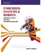
Book tittle: Embedded Systems and Robots Projects Using The 8051 Microcontroller
Author: Subrata Ghoshal
Project tittle: Maze-Solving Robot Using Wall-Following Algorithm
 |
Hardware Development
The maze-solving robot by Subrata Ghoshal used 2 units of toy cars, each powered by a single DC motor. The toy cars were cut into half and joined together to obtain a differential drive required to turn the car clockwise or anticlockwise. LDR’s were used for sensing the sidewalls while a touch sensor, a type of mechanical switch generally used in the computer keyboard was used to sense the front wall. The mechanical switch was used due to its cost-effectiveness and lesser number of hardware parts needed to make it function compared to LDR. Extra LDRs (ALARM LDR) were used on both sides of the robot to measure the proximity of the wall being followed. If the wall is too close, it would immediately be activated and sent signal accordingly. Otherwise, it should remain switched off. The robot was powered by 6 V power cell for motor and 9 V power cell with 7805 voltage regulator to supply a regulated 5 V DC power to the controller circuit. The controller circuit consists of AT89C2051 as the microprocessor.
The size of the robot is crucial to allow smoother negotiations through bends and turns. According to the designer, the size of the robot should not be more than one-fourth of the cell size. That is, for a maze with 180 mm x 180 mm grid, the robot size should be 90 mm x 90 mm or less at its base.
Software Development
Most of the time, the robot would move forward following a wall. The speed was controlled using Pulse Width Modulation (PWM) at 50% duty cycle. In case of reverse movements which adopted when the robot confronts a wall, slower speed is desirable and PWM is applied. For right and left turns, PWM is not necessary; only one motor is moved with full speed, while the other is not activated at all.
To ensure that the turn angles are exactly equal to 90º, the concept of time constant is used. Trial-and-error method is used to find the accurate time constant value. To finalize the time constant value for a 90º rotation, the robot is allowed to move forward for some time and then take a turn. The whole process is then repeated again and again (infinite loop). If the time constant adopted for this process is correct, then the robot would be moving along a perfect square for at least fifty loops. This time constant depends upon various parameters such as the make of the motor, its operating voltage, self-weight of the robot and friction against the floor.
The touch sensor is interfaced with INT0 input of the controller.
The overall program structure started with reset initialization followed by checking port 1.1 jumper setting to determine either to follow right wall or left wall, and start moving forward with PWM. The program then enters into an infinite main loop where the existence of a sidewall is continuously sensed during the forward movement. In the absence of any wall at its side, the robot would perform turning operation. Whenever the robot encounters a front wall, the INT0 interrupt service routine takes over the charge of reversing the robot and then turning it. Finally, the robot is set for forward operation and the duty of the INT0 interrupt is complete.
No comments:
Post a Comment